
In 2004, Larry became aware of a new modular layout system being promoted in the USA. It was called Free-mo, named after a similar European organisation. The concept is to create a modular layout that can be assembled in a plethora of variations, with modules constructed by a multitude of builders, with a view towards operating prototypical trains through a realistic setting. As is demonstrated below by the European organisation, one massive layout operated by many enthusiasts is possible.
The fundamental goals of Free-mo are to:
Free-mo is the best in modular model railroading. Free-mo was developed to eliminate the monotony of running trains around and around a double or even a triple track mainline. Free-mo operates like a permanent or sectional layout but still retains its modularity. Free-mo is actually more "modular" than existing double track standard modules are, because of the flexibility designed into Free-mo. Free-mo layouts are primarily operated with a single track mainline in point to point, point to loop, or loop to loop variations. Broad curves with a minimum radius of 42 inches is required; however broader curves are encouraged. Layout sizes can vary to any size conceivable. The Free-mo mainline is centred on a two foot end plate so modules can be rotated 180 degrees and still mate up to the adjacent module without modification to wiring or track. The Free-mo mainline runs on code 83 rail, and is controlled by a Digitrax DCC system.
Free-mo enables the modeller’s creativity to shine through. No longer is one confined to constructing 2 foot wide rectangular modules, 4, 6, or 8 feet long. In fact rectangular modules are strongly discouraged. Modellers may build to suit their own needs and dreams, or to show off or improve their modelling skills, as long as they remain within the constraints of the Free-mo design.
When building Free-mo modules, one must follow the standards laid out at Free-mo in order to ensure compatibility with other modules. The standards are meant to ensure that a module built by one person will correctly and fully connect to a module built by another person, without any difficulty. The standards include:
Several groups have taken the "standard" standards and expanded on them to raise the bar of their own modelling. Both Northern California Free-mo and Free-mo SLO have excellent web sites that provide immense amounts of information and techiniques, plus hints and tips they have developed. Other groups throughout North America have continued the tradition. Links to their web sites can be found through the Free-mo web site. One group based in Alberta, Calgary Free-mo, provided the initial inspiration to the Chilliwack group to commence construction of Coldslap Yard.
Coldslap Free-mo has a few recommended practices designed to encourage both a high standard of modelling and consistency among our own group:
Please refer to our recommended paints document, our electrical document, our adjustable legs design, our skirting document, and our module specifcations document for guidance.
Later in this section you will find references to a BoosterBox designed and contructed by Larry, to power a separate power district. For a complete article and plans to construct a BoosterBox, refer to the BoosterBox Construction document for guidance.
Our most recent diversion is along the path of signalling. We are currently installing signalling electronics under the modules, as well as signal masts on the tops of approriate modules, following the guidance of the California group. Gregg Fuhrimann designed a Modular Signal System (MSS) that has proven functional on Free-mo modules. At this time, we are primarily using products designed and manufactured by Model Railroad Signal Systems of Nanaimo BC (Adrien Poiron), augmented by detection boards from NCE and Team Digital. These products have been designed to be compatible with Fuhrimann's MSS specifications. We also intend to investigate the products offered by Signalogic Systems of Edmonton AB (Kevin Rudko) whenever possible. Kevin has been working with Calgary Free-mo for several years to develop his products. Signalling will add a new level of realism to our already fantastic modules.
If you have any further questions about our projects, goals, standards, or Free-mo in general, please refer to our contact page to locate people eager to assist you. We are always seeking serious modellers to help expand the layout possiblities. We will be pleased to welcome you with your fully-compliant module at a Free-mo meet.
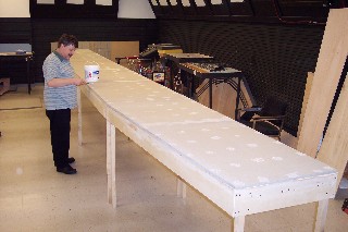
Once bitten by the Free-mo bug, a sub-group of 10 club members each contributed a sizeable sum of cash to commence construction of a classification yard to form the anchor for a Free-mo layout. The yard is made up of four, seven-foot long sections, plus two, three-foot long sections, with double-track Free-mo compatible connections at the far ends. The framework was constructed, the table top was laid, and the four sections bolted together. Then track was laid accross the length of the entire unit. The power bus and feeders were installed next, followed by 37 Tortoise switch motors, controlled via DCC and push buttons. The design has essentially symetrical ends, and therefore can be set up as a flow-through yard, or can be split into two stub-end yards. Please follow the story below to learn how we went about the process.
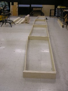 |
After studying the recommendations of other groups, we decided to use 3/4" birch cabinet grade plywood for the endplates and general framework. We acquired 3 sheets and had a friend slice them into long strips: 6 inches wide for the endplates, and 5 1/2 inches wide for the sides. They were laid out on the floor to create 4 sections for the yard module, beveled the joints accordingly, and glued and screwed them to create 4 frames. To our surprise, once the sheets were sliced lengthwise, the individual strips seemed to curve. This was corrected at a later step in the process. |
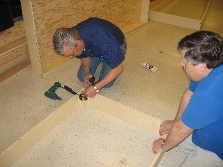 |
We next built 4 pockets from the 5 1/2 inch strips for each of the 4 sections, and glued and screwed them into the corners. These pockets hold the adjustable height legs. |
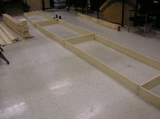 |
Our next task was to clamp each of the sections together into a single module framework. We had already decided that the best and quickest way to attach the sections together for operating was to bolt them together. So once we had the sections aligned and clamped, we drilled 7/16 inch holes through the pairs of endplates: 2 on the Free-mo double-track endplates, and 3 on the internal endplates because they are 34 inches wide. |
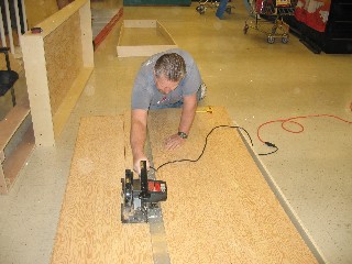 |
In order to stabilise the entire structure, and to square each of the sections, we cut 1/2 inch fir plywood to size, and then glued and screwed it to the sectional framework. This layer provided the sub-roadbed for the yard module. |
 |
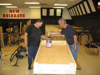
After much discussion about the best roadbed material to use, and the availability of some Homasote sheets at the local building materials store, we decided that Homasote would provide the best surface on which to install track. So we acquired the sheets, and cut them to match the top deck of each of the 4 sections. A generous coating of glue was spread between the plywood and the Homasote, and the Homasote was screwed to the plywood. To provide a relatively smooth surface, the screw heads and Homasote seams were puttied and sanded. Also some ripples in the Homasote required sanding to smooth the surface prior to track laying. |
 |
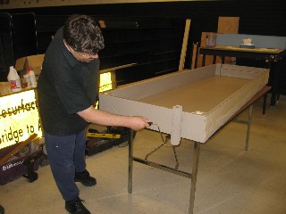
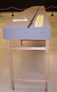
In order to seal the framework and benchwork wood, we decided to paint the underside of the yard sections with the base coat colour (Dried Bark). We also felt that many people would want to inspect our construction and wiring, so the painted wood would add to the appearance of excellence. |
 |
Similarly to protect the wood, we painted the endplates, again with Dried Bard paint. However, we have since painted the end plates with TREMCLAD flat black to camoflage the ends when a mini-mo is attached for a operating session. The TREMCLAD has proven its value because it allows the modules to be come apart at the end of a show without sticking together and breaking the wood; any latex paint seems to stick no matter how long it has cured. TREMCLAD is a solvent-based paint, so needs to be applied in a well-ventilated location. The Homasote roadbed was painted with two coats of Dried Bark, thinned 50% with water. |
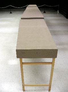 |
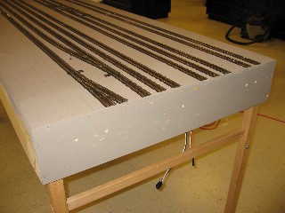
The completed framework, benchwork, and roadbed are ready to have track installed. 1/16 inch hardboard has since been glued to the long sides to create a smooth fascia. It has been painted with Piano black latex paint. |
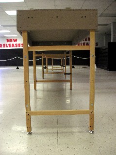 |
Harry found a description for making adjustable height legs, and he proceeded to construct enough leg sets for the 4 section yard (plus a few more for individually-owned modules). He made them of dressed 1x2 fir lumber. Each pair is bolted with 4 bolts. By installing the bolts in their lower positions, a nominal track height of 42 inches is achieved. However, when installing the bolts in their higher positions, a nominal track height of 50 inches is achieved. Each leg is fitted with a screw-type adjustable foot in a T-nut to provide 3 inches of height adjustment to account for uneven flooring surfaces. The legs are so beautiful that we cannot bring ourselves to paint them! |
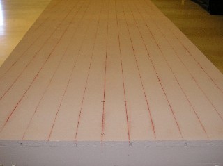 |
Before starting to lay any track, we first snapped chalk lines at 2 inch centres from the two main line positions over the entire 28 foot length of the yard module. Free-mo standards call for 2 inch spacing between parallel straight tracks. The chalk lines would also allow us to better position the tracks. |
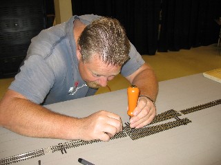 |
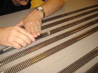
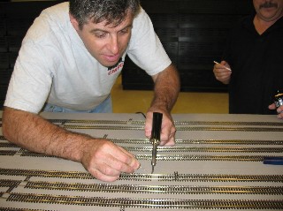
There are two main lines that travel all the way through the yard. We began by laying one track along its chalk mark, while at the same time positioning the turnouts that would enter and leave that track. After some discussion, it was determined that turnouts should be spiked down to allow for potential removal in case repairs were to become necessary. The flex track lengths, however, were glued to the roadbed. |
 |
A bead of Weldbond glue was laid down the centre line, and spread by finger approximately 1/2 inch to each side. The flex track was gently laid into the glue and roughly positioned. The track was left for some 5 minutes, until the glue began to firm, and then a straight edge as long as possible was placed beside the ties. The track was nudged into alignment, and great care was taken to ensure this first track was as perfectly straight as possible. |
 |
Our careful efforts were rewarded with a nearly laser-straight main line. It would form the base to which all other tracks were aligned. |
 |
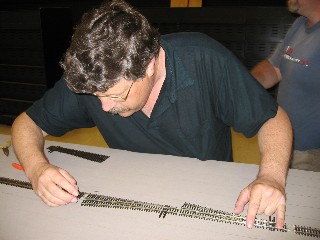
We next laid the second main line through the yard, using 2 inch track separation gauges, to ensure that the two main lines were parallel. Again, we spiked the turnouts into position, and glued the flex track with Weldbond. |
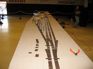 |
We proceeded to lay the yard ladders, first on one side of the main and then on the other side. We did the same at the opposite end of the yard, all in accordance with the track plan previously drawn (although some slight modifications became necessary along the way). |
 |
We then glued flex track between the ladders to complete the track laying. We left several turnouts leading off the yard tracks, for spurs and service areas, until a later date. |
 |
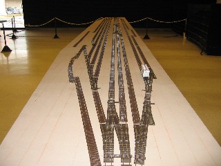
All the track (except for some spurs) is laid. |
 |
Once all the track glue was dried, a diamond cut-off wheel was chucked into a Dremel flex shaft, and the rails over each module section were cut through, while attempting to maintain squareness and perpendicularity. The cuts were lightly dressed with a jeweller's file to remove any burrs. |
 |
The 4 sections were separated. Because of the way the track was laid and cut through, we have no need to insert fitter rails between the yard sections when we set up. Set up and knock down time is greatly reduced. We must, however, exercise great caution when moving the sections, as the rail ends are dangerously close to the section ends. We have experienced a few mishaps! |
 |
Next came a discussion surrounding the best method to throw the turnouts. We considered ground throws, but decided it would be too dangerous to reach into the middle of the yard to throw a turnout, and the alternative of building extension rods was both cumbersome and unattractive. We decided on using Tortoise motors, as they are the proven industry standard. An Internet order resulted in a carton of 37 Tortoises being delivered to Chilliwack. There was some concern about the strength of the throw rod being sufficient to overcome the point spring in the Peco turnouts, and in fact, a quick experiment proved there was a strength issue. It was suggested that we remove the point springs, but that option was declined as it would alter the turnouts too severely. An Internet search provided a recommendation to change the throw rod wire to a heavier gauge piano wire. The theory was proven satisfactory, so we set about altering the Tortoises by carefully drilling the holes slightly larger to accomodate the piano wire. |
 |
We also chose the Tortoises because of their internal switch contacts that we could use to power the Electrofrogs in the Peco turnouts. Powered frogs are a requirement of the Free-mo standards, because relying on power to flow via the points is considered too risky and unreliable. Here are 14 mounted Tortoises awaiting wiring. We fed one track bus to one Tortoise contact, and the other track bus to the opposite contact. The third contact was connected to the wire hanging down from the Peco Electrofrog. We then had to test to ensure that the frog was powered correctly with the alignment of the points, swapping connections from the track bus if required. |
 |
Once the track was laid, we proceeded to solder the rail joiners into place, to ensure electrical conductivity. Then ties were sanded to thin them, slid underneath the rail joints, and glued into place. |
 |
At frequent intervals for straight sections (far more often than is "required"), and to each side of each turnout, 22 gauge stranded feeders were dropped through the subroadbed. |
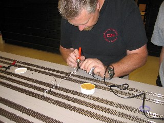 |
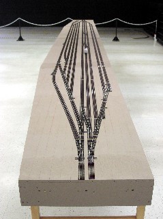
The feeder tops were formed, tinned, and soldered to the outer rail webs. Following this stage, all the track on both sides was airbrushed with an acrylic Roof Brown paint in accordance with the Free-mo standards. We sprayed the paint about one foot at a time, and then very quickly before the paint dried, wiped the railheads with a damp cloth to remove most of the paint from the railheads. Once the paint dried, the railheads were polished using a PECO track cleaner. |
 |
Then the feeders were cut to length and soldered to the 12 gauge stranded power bus wires that run the length of each yard section. The black and white pair of wires in this photograph are the 12 gauge stranded track bus wires. The red and white pair are the 14 gauge stranded accessory bus wires. The accessory circuit carries 15 volts AC as required by the Free-mo standards. An alternative for this circuit is to carry a separate DCC power signal instead. It is said there are certain benefits to powering the accessory bus with DCC, but the benefits are as yet unclear to us. All modules have received the required conversion treatment to Anderson Power Pole connectors. |
 |
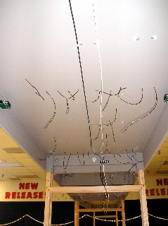
Larry had previously purchased a 1000-foot roll of black 6-conductor cable from Digikey. From this roll, pieces were cut to fit and RJ12 connectors crimped onto the cable ends. The cables were mounted to the yard sections to connect the Digitrax components. |
 |
We were all quite proud of ourselves for our successful completion of the yard. We connected it all together and tested it. All worked beautifully, except how were we to actually throw the turnouts? The Free-mo standards say that we could use DCC to throw the turnouts, but if we did so, we also needed to provide pushbuttons to throw the turnouts, to accomodate those with more basic throttles in hand. Off to the Internet again to conduct some research. We needed stationary decoders to accomplish DCC control, and we decided that this would indeed be the most elegant solution. |
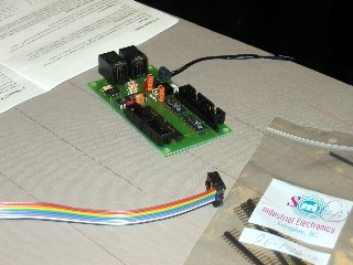 |
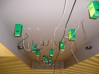
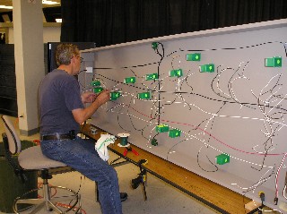
We located Team Digital SRC8 circuit boards, each of which is capable of controlling 8 Tortoise motors. We acquired 4 circuit boards, wired them to the Tortoises, and programmed the turnout numbers. They worked well, but because te SRC8 boards output only 5 volts, the Tortoises moved VERY slowly. In time, our group felt the reaction time was too slow, so we have since replaced the SRC8 boards with 8 Digitrax DS64 sationary decoders. Pushbutton panels for both sides of each yard ladder were constructed, and have proven simple and effective to control the turnouts. The DS64 decoders have the capability to create routes, so we have programmed the yard track turnouts with routes that can be operated from a compatible throttle. |
 |
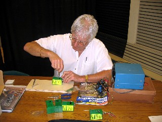
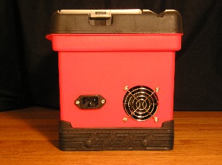
Some inspiration gained from the Internet led Larry to construct what he calls a Digibox to contain the Digitrax Super Chief command station. The goal was to install all the required components into a compact, transportable container, that was also quick and easy to connect to the layout. A suitable tool box was located (Benchmark brand from Home Hardware). It has nearly vertical sides to allow for component attachment, and as a bonus, is red and black just like Digitrax colours. A piece of plywood was cut to fit the bottom of the tool box and painted black. On it were attached the command station, power supply, and surge protector/power bar. The large white adapter provides 16 VAC to the accessory power bus, while the smaller black adapter provides 12 VDC to the cooling fan. The white adapter has since been replaced by a Digitrax PS-315 to provide 3 amps of power to the accessory bus. |
 |
The left end of the box was drilled and cut to install a power-in socket, a cooling fan, and a Cinch Jones panel socket for the program track output. |
 |
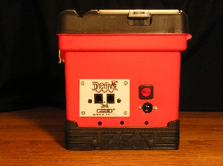
The right end of the box was drilled and cut to install a UP5 panel, accessory power (speaker-type) connector, and four Cinch Jones sockets for track power outputs. Adapter cords have been constructed to convert Cinch Jones outputs to Anderson Power Pole connectors, to comply with current Free-mo electrical standards. There is room in the box to install a PM42 in the future, should we determine it desireable: hence the four track power outputs. We merely plug a 110 VAC power cord into the left end, plus track power bus, loconet, and accessory power into the right end, and we are ready to run in only minutes. |
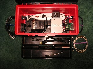 |
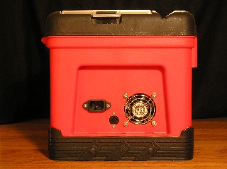
Larry later determined that a booster to create a separate power district was desireable, so he constructed what he calls a Boosterbox to contain the Digitrax Empire Builder for booster operation. The goal again was to install all the required components into a compact, transportable container, that was also quick and easy to connect to the layout. A smaller tool box was located (Benchmark brand from Home Hardware). It also has nearly vertical sides to allow for component attachment, and matches its larger brother. A piece of plywood was cut to fit the bottom of the tool box and painted black. On it were attached the command station, power supply, and surge protector/power bar. The black adapter provides 12 VDC to the cooling fan. |
 |
The left end of the box was drilled and cut to install a power-in socket and a cooling fan |
 |
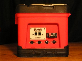
The right end of the box was drilled and cut to install a UP5 panel and a Cinch Jones socket. The switch above the socket allows the booster to be set for auto-reverse mode when needed. We merely plug a 110 VAC power cord into the left end, plus track power bus and loconet into the right end, fire the unit up after the command station, and we are ready to run. At the Big Valley 2006 meet, and following some Yahoogroup discussions, we learned that the Digitrax UP5 panel does not pass the Railsync lines from the rear jacks through to the front jacks. Therefore, when we attempted to connect the Boosterbox into the main group's power districts, it could not communicate with the rest of the Digitrax system. To solve the problem, Larry removed the UP5 from the box and replaced it with an NCE UTP throttle panel. The NCE panel allows all six of the Loconet connections to flow between the rear and front jacks. A recent test confirmed that the revised design does work. Larry performed the same modification to the Digibox command station. The green sockets on the Boosterbox allow the ground wire connection to be daisy-chained to the green socket on the Digibox. For a complete article and plans to construct a BoosterBox, refer to the BoosterBox Construction document for guidance. |
The scenery on Coldslap Yard is essentially complete. That is, unless some member decides to add a detail or two, we have completed:
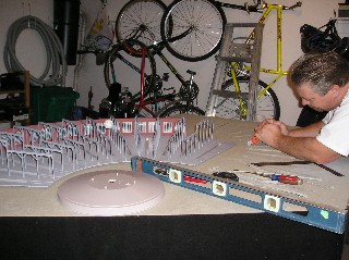
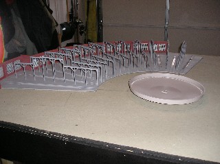
James built an engine service facility to be attached to the side of one section of the yard. It includes a 12 stall roundhouse and turntable, plus various structures and pieces of equipment to service steam locomotives.
 |
The basic structure of a Walthers roundhouse was constructed, and the slots in the deck were cut to allow the inspection pits to drop in. The roundhouse will be glued to the deck in due course. |
 |
Once the floor of the roundhouse was settled, a line was drawn from the centre of each end track, so that they crossed each other, to locate the centre of the turntable pit. |
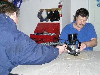 |
Several passes of a router with a tramel point were made in order to cut a circle through the Homasote and plywood, slightly smaller in diameter than the lip of the Walthers turntable pit. |
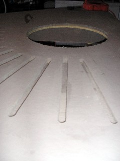 |
Some slight sanding of the edge of the turntable hole was done to smooth its surface and allow the turntable to sink in gently, but fully. Then track was laid from the roundhouse bays to the edge of the pit. |
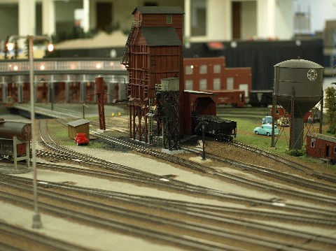 |
The ash pit, coal tower, and sand house were constructed and installed in their proper locations. Several tracks were laid to transport supplies into and out of the service area. |
 |
Larry built a diesel service facility near the roundhouse. It includes fuel and water racks, plus a sand tower. A two-stall diesel shop allows for minor locomotive repairs. New tracks were laid to the coal tower, ash pit, and sand house. The entire engine service area was nearing completion. |
 |
Other members of the group are working on their own modules, for example this mini-mo (named Muzzup) often used as a bridge piece, or a switching lead out of the yard. |
 |
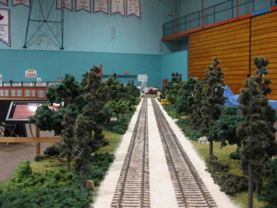
For most modules in the group, the scenery is a Pacific Northwest green-treed motif, as evidenced by the 3-section module "Chemchill" built by Harry S and Dick. |
 |
The other major module set is the 10-section "Deadman Flats" built by Harry H. Harry continues to add scenic elements. Unfortuantely Harry passed away in March 2020. His wife, Doris, was very generous by donating the loop set to Coldslap Free-mo in exchange for assisting her in selling Harry's other railroad equipment. In recognition of Harry's contributions and of Doris' donation, we have renamed the loop "Hardor" and have since added buildings and scenery to complete the module set. Also, Larry has constructed an entrance module named "Hardor X" to further develop the loop. |
| The initial design of the yard was that it would be in 4 sections each 7 feet long. The two yard ladder ends would be mirror images of each other, from a framework point of view. Therefore, from the start, we intended for the 4 yard sections to be "crated" into 2 units for transportation. | |
| We constructed end plates for transportation so that they could be bolted to the Free-mo endplates and one yard section could be flipped over above its matching yard section. | |
| The sections were clamped into place and a drill was run through the endplate bolt holes to create matching holes in the transport plates. | |
| When the 2 yard sections are bolted to the transport plates, a secure unit is created for shipping. We also made some heavy duty casters that slip into the leg pockets, so that the unit can be rolled over a smooth surface. We can even stack the two units together to roll carefully over a very smooth surface. This entire design worked well for us in the beginning, however, age and agility have caught up with us. Given that we found moving two yard sections in one package was extremely challenging, we decided to separate the sections by redesigning the end plates for transportation. Now we can move one section at a time much more easily. | |
| Many of the group's modules are transported in Larry's trailer and truck. We have developed quite an efficient loading, packing, and unloading methodology to get to our desitination safely. |
Please see the coming events page for our future plans. We hope to see you at one of the events.